Data Networks
Sharing data through the use of floppy disks/cd/dvd/flash drives etc are not an efficient or cost-effective manner.
Businesses needed a solution that would successfully address the following three problems:
• How to avoid duplication of equipment and resources
• How to communicate efficiently
• How to set up and manage a network
Businesses realized that networking technology could increase productivity while saving money.
Networking Devices
Equipment that connects directly to a network segment is referred to as a device.
These devices are broken up into two classifications.
1. End-user devices
2. Network devices
• End-user devices include computers, printers, scanners, and other devices that provide services directly to the user.
• Network devices include all the devices that connect the end-user devices together to allow them to communicate.
Network Interface Card
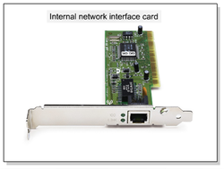
A network interface controller (also known as a network interface card, network adapter, LAN adapter and by similar terms) is a computer hardware component that connects a computer to a computer network.
Whereas network interface controllers were commonly implemented on expansion cards that plug into a computer bus, the low cost and ubiquity of the Ethernet standard means that most newer computers have a network interface built into the motherboard.
Hub
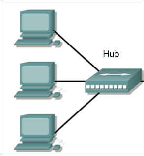
A hub is a device for connecting multiple twisted pair or fiber opticEthernet devices together and making them act as a single network segment. Hubs work at the physical layer (layer 1) of theOSI model.
The device is a form of multiport repeater. Repeater hubs also participate in collision detection, forwarding a jam signal to all ports if it detects a collision.
Hubs also often come with a BNC and/or Attachment Unit Interface (AUI) connector to allow connection to legacy 10BASE2 or10BASE5 network segments. The availability of low-priced network switches has largely rendered hubs obsolete but they are still seen in older installations and more specialized applications
Switch
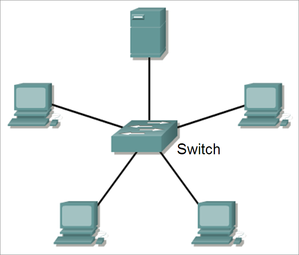
A network switch or switching hub is a computer networking device that connects network segments.
The term commonly refers to a multi-port network bridge that processes and routes data at the data link layer (layer 2) of the OSI model. Switches that additionally process data at the network layer (Layer 3) and above are often referred to as Layer 3 switches or multilayer switches.
The term commonly refers to a multi-port network bridge that processes and routes data at the data link layer (layer 2) of the OSI model. Switches that additionally process data at the network layer (Layer 3) and above are often referred to as Layer 3 switches or multilayer switches.
Router
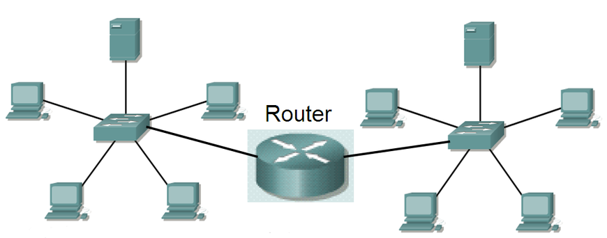
A router is a device that forwards data packets between telecommunications networks, creating an overlay internetwork. A router is connected to two or more data lines from different networks. When data comes in on one of the lines, the router reads the address information in the packet to determine its ultimate destination. Then, using information in its routing table or routing policy, it directs the packet to the next network on its journey or drops the packet. A data packet is typically forwarded from one router to another through networks that constitute the internetwork until it gets to its destination node.
- Routers are used to connect networks together
- Route packets of data from one network to another
- By default Routers breaks the broadcast domain
The most familiar type of routers are home and small office routers that simply pass data, such as web pages and email, between the home computers and the owner's cable or DSL modem, which connects to the Internet (ISP). However more sophisticated routers range from enterprise routers, which connect large business or ISP networks up to the powerful core routers that forward data at high speed along the optical fiber lines of the Internet backbone.
Inter-networking Devices
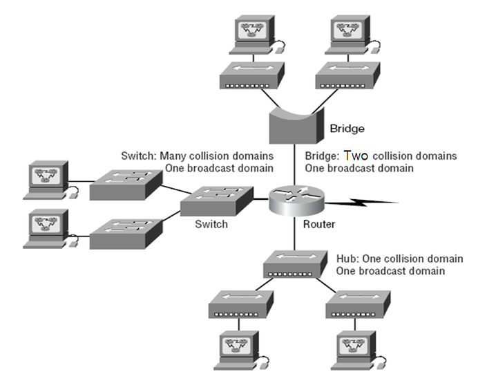
When you looked at Figure, did you notice that the router is found at center stage, and that it connects each physical network together? We have to use this layout because of the older technologies involved–—bridges and hubs. Once we have only switches in our network, things change a lot! The LAN switches would then be placed at the center of the network world and the routers would be found connecting only logical networks together. If I’ve implemented this kind of setup, I’ve created virtual LANs (VLANs).
On the top network in Figure, you can see that a bridge was used to connect the hubs to a router. The bridge breaks up collision domains, but all the hosts connected to both hubs are still crammed into the same broadcast domain. Also, the bridge only created two collision domains, so each device connected to a hub is in the same collision domain as every other device connected to that same hub. This is pretty lame, but it’s still better than having one collision domain for all hosts.
The three hubs at the bottom that are connected also connect to the router, creating one humongous collision domain and one humongous broadcast domain. This makes the bridged network look much better indeed.
