Network Topologies
Network topology defines the structure of the network.
Network topology is the layout pattern of interconnections of the various elements (links, nodes, etc.) of a computer or biological network. Network topologies may be physical or logical. Physical topology refers to the the physical design of a network including the devices, location and cable installation.
Logical topology refers to how data is actually transferred in a network as opposed to its physical design. In general physical topology relates to a core network whereas logical topology relates to basic network.
Topology can be understood as the shape or structure of a network. This shape does not necessarily correspond to the actual physical design of the devices on the computer network. The computers on a home network can be arranged in a circle but it does not necessarily mean that it represents a ring topology. Any particular network topology is determined only by the graphical mapping of the configuration of physical and/or logical connections between nodes. The study of network topology uses graph theory. Distances between nodes, physical interconnections, transmission rates, and/or signal types may differ in two networks and yet their topologies may be identical.
- One part of the topology definition is the physical topology, which is the actual layout of the wire or media.
- The other part is the logical topology , which defines how the media is accessed by the hosts for sending data.
Point-to-point Topology
The simplest topology is a permanent link between two endpoints. Switched point-to-point topologies are the basic model of conventional telephony. The value of a permanent point-to-point network is unimpeded communications between the two endpoints. The value of an on-demand point-to-point connection is proportional to the number of potential pairs of subscribers, and has been expressed as Metcalfe's Law.
Permanent (dedicated) :
Easiest to understand, of the variations of point-to-point topology, is a point-to-point communications channel that appears, to the user, to be permanently associated with the two endpoints. A children's tin can telephone is one example of a physical dedicated channel.
Within many switched telecommunications systems, it is possible to establish a permanent circuit. One example might be a telephone in the lobby of a public building, which is programmed to ring only the number of a telephone dispatcher. "Nailing down" a switched connection saves the cost of running a physical circuit between the two points. The resources in such a connection can be released when no longer needed, for example, a television circuit from a parade route back to the studio.
Switched :
Using circuit-switching or packet-switching technologies, a point-to-point circuit can be set up dynamically, and dropped when no longer needed. This is the basic mode of conventional telephony.
Bus Topology
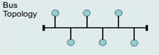
A bus topology uses a single backbone cable that is terminated at both ends.
All the hosts connect directly to this backbone.
In local area networks where bus topology is used, each node is connected to a single cable. Each computer or server is connected to the single bus cable. A signal from the source travels in both directions to all machines connected on the bus cable until it finds the intended recipient. If the machine address does not match the intended address for the data, the machine ignores the data. Alternatively, if the data does match the machine address, the data is accepted. Since the bus topology consists of only one wire, it is rather inexpensive to implement when compared to other topologies. However, the low cost of implementing the technology is offset by the high cost of managing the network. Additionally, since only one cable is utilized, it can be the single point of failure. If the network cable breaks, the entire network will be down.
Linear bus
The type of network topology in which all of the nodes of the network are connected to a common transmission medium which has exactly two endpoints (this is the 'bus', which is also commonly referred to as the backbone, or trunk) – all data that is transmitted between nodes in the network is transmitted over this common transmission medium and is able to be received by all nodes in the network simultaneously.[1]
Note: The two endpoints of the common transmission medium are normally terminated with a device called a terminator that exhibits the characteristic impedance of the transmission medium and which dissipates or absorbs the energy that remains in the signal to prevent the signal from being reflected or propagated back onto the transmission medium in the opposite direction, which would cause interference with and degradation of the signals on the transmission medium.
Distributed bus
The type of network topology in which all of the nodes of the network are connected to a common transmission medium which has more than two endpoints that are created by adding branches to the main section of the transmission medium – the physical distributed bus topology functions in exactly the same fashion as the physical linear bus topology (i.e., all nodes share a common transmission medium).
Notes:
- All of the endpoints of the common transmission medium are normally terminated.
- The linear bus topology is sometimes considered to be a special case of the distributed bus topology – i.e., a distributed bus with no branching segments.
- The physical distributed bus topology is sometimes incorrectly referred to as a physical tree topology – however, although the physical distributed bus topology resembles the physical tree topology, it differs from the physical tree topology in that there is no central node to which any other nodes are connected, since this hierarchical functionality is replaced by the common bus
Ring Topology
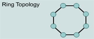
A ring topology connects one host to the next and the last host to the first.
This creates a physical ring of cable
A network topology that is set up in a circular fashion in which data travels around the ring in one direction and each device on the right acts as a repeater to keep the signal strong as it travels. Each device incorporates a receiver for the incoming signal and a transmitter to send the data on to the next device in the ring. The network is dependent on the ability of the signal to travel around the ring.
Star Topology
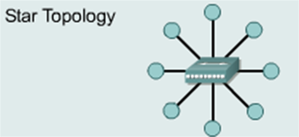
A star topology connects all cables to a central point of concentration.
In local area networks with a star topology, each network host is connected to a central hub with a point-to-point connection. All traffic that traverses the network passes through the central hub. The hub acts as a signal repeater. The star topology is considered the easiest topology to design and implement. An advantage of the star topology is the simplicity of adding additional nodes. The primary disadvantage of the star topology is that the hub represents a single point of failure.
Notes:-
- A point-to-point link (described above) is sometimes categorized as a special instance of the physical star topology – therefore, the simplest type of network that is based upon the physical star topology would consist of one node with a single point-to-point link to a second node, the choice of which node is the 'hub' and which node is the 'spoke' being arbitrary.
- After the special case of the point-to-point link, as in note above, the next simplest type of network that is based upon the physical star topology would consist of one central node – the 'hub' – with two separate point-to-point links to two peripheral nodes – the 'spokes'.
- Although most networks that are based upon the physical star topology are commonly implemented using a special device such as a hub or switch as the central node (i.e., the 'hub' of the star), it is also possible to implement a network that is based upon the physical star topology using a computer or even a simple common connection point as the 'hub' or central node.[citation needed]Star networks may also be described as either broadcast multi-access or nonbroadcast multi-access (NBMA), depending on whether the technology of the network either automatically propagates a signal at the hub to all spokes, or only addresses individual spokes with each communication.
Extended Star & Distributed Star

Extended Star
An extended star topology links individual stars together by connecting the hubs and/or switches. This topology can extend the scope and coverage of the network.
Distributed Star
A type of network topology that is composed of individual networks that are based upon the physical star topology connected together in a linear fashion – i.e., 'daisy-chained' – with no central or top level connection point (e.g., two or more 'stacked' hubs, along with their associated star connected nodes or 'spokes')
Mesh Topology
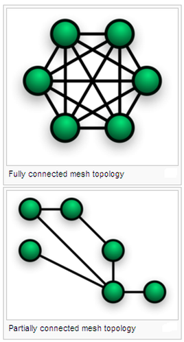
- A mesh topology is implemented to provide as much protection as possible from interruption of service.
- Each host has its own connections to all other hosts.
- Although the Internet has multiple paths to any one location, it does not adopt the full mesh topology.
The value of fully meshed networks is proportional to the exponent of the number of subscribers, assuming that communicating groups of any two endpoints, up to and including all the endpoints, is approximated by Reed's Law.
Fully connected
Fully connected mesh topologyThe number of connections in a full mesh = n(n - 1) / 2.
Partially connected
Partially connected mesh topologyThe type of network topology in which some of the nodes of the network are connected to more than one other node in the network with a point-to-point link – this makes it possible to take advantage of some of the redundancy that is provided by a physical fully connected mesh topology without the expense and complexity required for a connection between every node in the network.
Note:
- The physical fully connected mesh topology is generally too costly and complex for practical networks, although the topology is used when there are only a small number of nodes to be interconnected.
- In most practical networks that are based upon the partially connected mesh topology, all of the data that is transmitted between nodes in the network takes the shortest path between nodes,[citation needed] except in the case of a failure or break in one of the links, in which case the data takes an alternative path to the destination. This requires that the nodes of the network possess some type of logical 'routing' algorithm to determine the correct path to use at any particular time.
Tree Topology
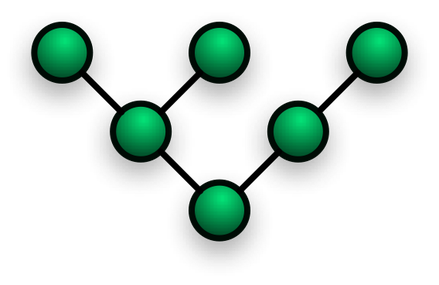
Among all the Network Topologies we can derive that the Tree Topology is a combination of the bus and the Star Topology. The tree like structure allows you to have many servers on the network and you can branch out the network in many ways. This is particularly helpful for colleges, universities and schools so that each of the branches can identify the relevant systems in their own network and yet connect to the big network in some way.A Tree Structure suits best when the network is widely spread and vastly divided into many branches. Like any other topologies, the Tree Topology has its advantages and disadvantages. A Tree Network may not suit small networks and it may be a waste of cable to use it for small networks. Tree Topology has some limitations and the configuration should suit those limitations.
Tree Network topology Benefits
The signals that are being transmitted by the root node are received by all the nodes at the same time. This increases the efficiency of the over all functioning of the network. The Tree Network topology can be extended easily to function and there are no limitations to how big it can be extended. Additional root nodes can be added and they can be interconnected within one single network.
Tree Network topology Benefits
- A Tree Topology is supported by many network vendors ad even hardware vendors.
- A point to point connection is possible with Tree Networks.
- All the computers have access to the larger and their immediate networks.
- Best topology for branched out networks.
- In a Network Topology the length of the network depends on the type of cable that is being used.
- The Tree Topology network is entirely dependant on the trunk which is the main backbone of the network. If that has to fail then the entire network would fail.
- Since the Tree Topology network is big it is difficult to configure and can get complicated after a certain point.
- There will be at least three levels of hierarchy in the Tree Network Topology and they all work based on the root node.
- The Tree Topology has two kinds of topology integral in it, the star and the linear way of connecting to nodes.
- The Tree Topology functions by taking into account the total number of nodes present in the network. It does not matter how many nodes are there on each level. Nodes can be added to any level of the hierarchy and there are no limitations a far as the total number of nodes do not exceed.
- The higher levels in the hierarchy are expected to perform more functions than the lower levels in the network.
The signals that are being transmitted by the root node are received by all the nodes at the same time. This increases the efficiency of the over all functioning of the network. The Tree Network topology can be extended easily to function and there are no limitations to how big it can be extended. Additional root nodes can be added and they can be interconnected within one single network.
Hybrid
Hybrid networks use a combination of any two or more topologies in such a way that the resulting network does not exhibit one of the standard topologies (e.g., bus, star, ring, etc.). For example, a tree network connected to a tree network is still a tree network topology. A hybrid topology is always produced when two different basic network topologies are connected. Two common examples for Hybrid network are: star ring network and star bus network.
A Snowflake topology is really a "Star of Stars" network, so it exhibits characteristics of a hybrid network topology but is not composed of two different basic network topologies being connected together.
- A Star ring network consists of two or more star topologies connected using a multistation access unit (MAU) as a centralized hub.
- A Star Bus network consists of two or more star topologies connected using a bus trunk (the bus trunk serves as the network's backbone).
A Snowflake topology is really a "Star of Stars" network, so it exhibits characteristics of a hybrid network topology but is not composed of two different basic network topologies being connected together.
Daisy chain
Except for star-based networks, the easiest way to add more computers into a network is by daisy-chaining, or connecting each computer in series to the next. If a message is intended for a computer partway down the line, each system bounces it along in sequence until it reaches the destination. A daisy-chained network can take two basic forms: linear and ring.
- A linear topology puts a two-way link between one computer and the next. However, this was expensive in the early days of computing, since each computer (except for the ones at each end) required two receivers and two transmitters.
- By connecting the computers at each end, a ring topology can be formed. An advantage of the ring is that the number of transmitters and receivers can be cut in half, since a message will eventually loop all of the way around. When a node sends a message, the message is processed by each computer in the ring. If a computer is not the destination node, it will pass the message to the next node, until the message arrives at its destination. If the message is not accepted by any node on the network, it will travel around the entire ring and return to the sender. This potentially results in a doubling of travel time for data.
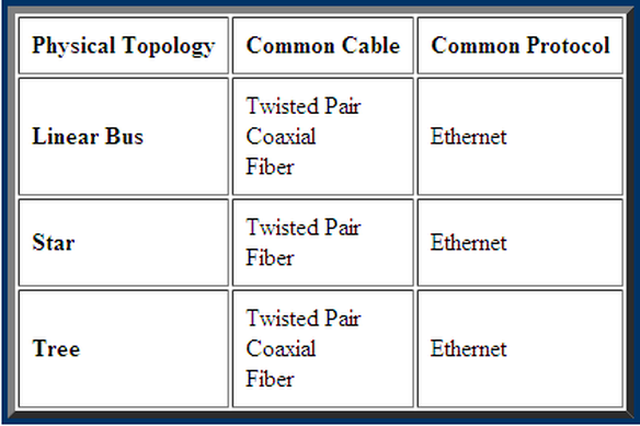
Summary Chart